PROJECT OVERVIEW.


Planning for an Intercept Bore
Once critical area of the project was that the sewer ran through a hill which, if open cut, would require trenches up to 12m deep over 300+ metres.
Diona engaged Pezzimenti in the concept stage of the design to see what was possible with respect to bore diameters and likely lengths of bores based on the ground conditions found in the geotech study for the Project – being solid shale.
From there, Diona selected suitable locations for shafts which were 340m apart. Knowing that it was not possible to bore that length from one end, they prepared both shafts for boring with the plan being an intercept bore.
Two tunnels create the 317m length required.
Boring commenced from the upstream end and was dry for the majority of the 197m. The completion of the first bore left a length of 120m to complete the intercept bore.
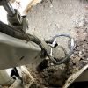
Boring commenced from the downstream end. When we were due to “break through”, a camera was sent from the upstream end to witness the cutters breaking through. The breakthrough was slightly off centre so the head continued to cut approx 5m past the break through point to ensure a smooth transition.
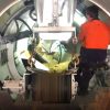
All rods were then retracted and the DN300mm GRP SN20,000 pipe was pushed up the bore from the top end on timber skids. Jacking / pushing load got to approx 5T which was well within the allowable jacking load.
A bulkhead was then built either end and the grout was poured from the bottom end.
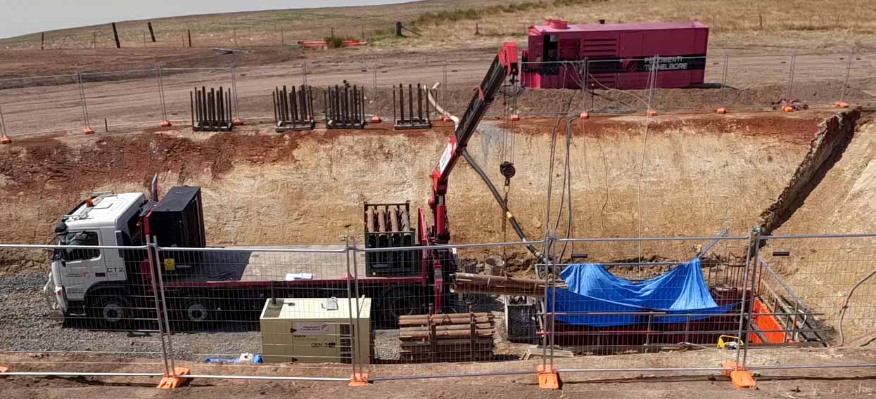
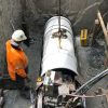
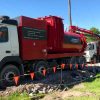
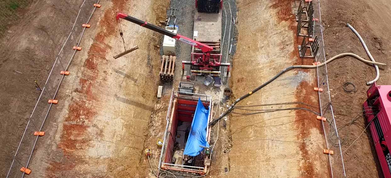
Site Setup at the 2nd shaft during operation. Crane truck lowers the drill rods into the shaft. The powerpack seen top right powers the drilling equipment in the shaft.
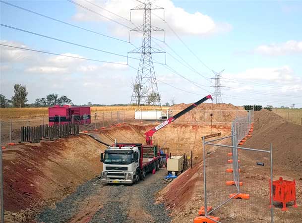
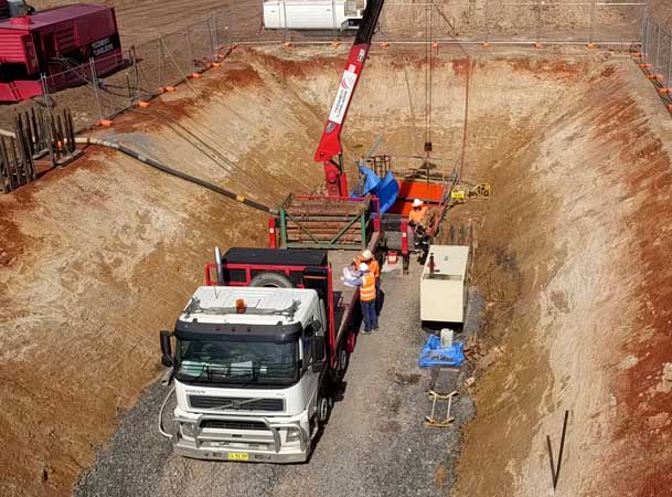
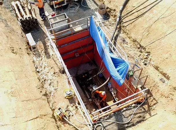
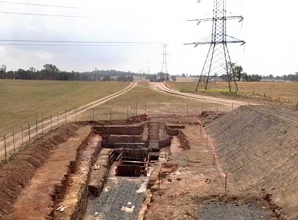
Shaft 1. 197m was tunnelled from this shaft first.
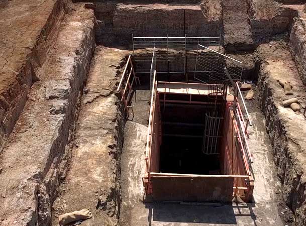
The ground was solid shale and the majority of the tunnel was bored without using water.
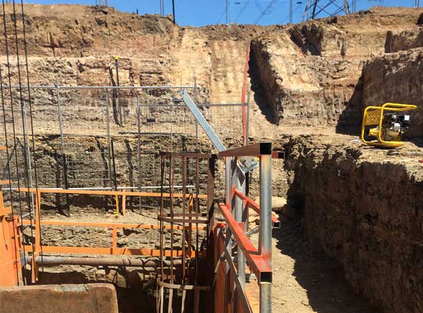
The depth for the shaft shows clearly why microtunnelling was the obvious method over open cut.
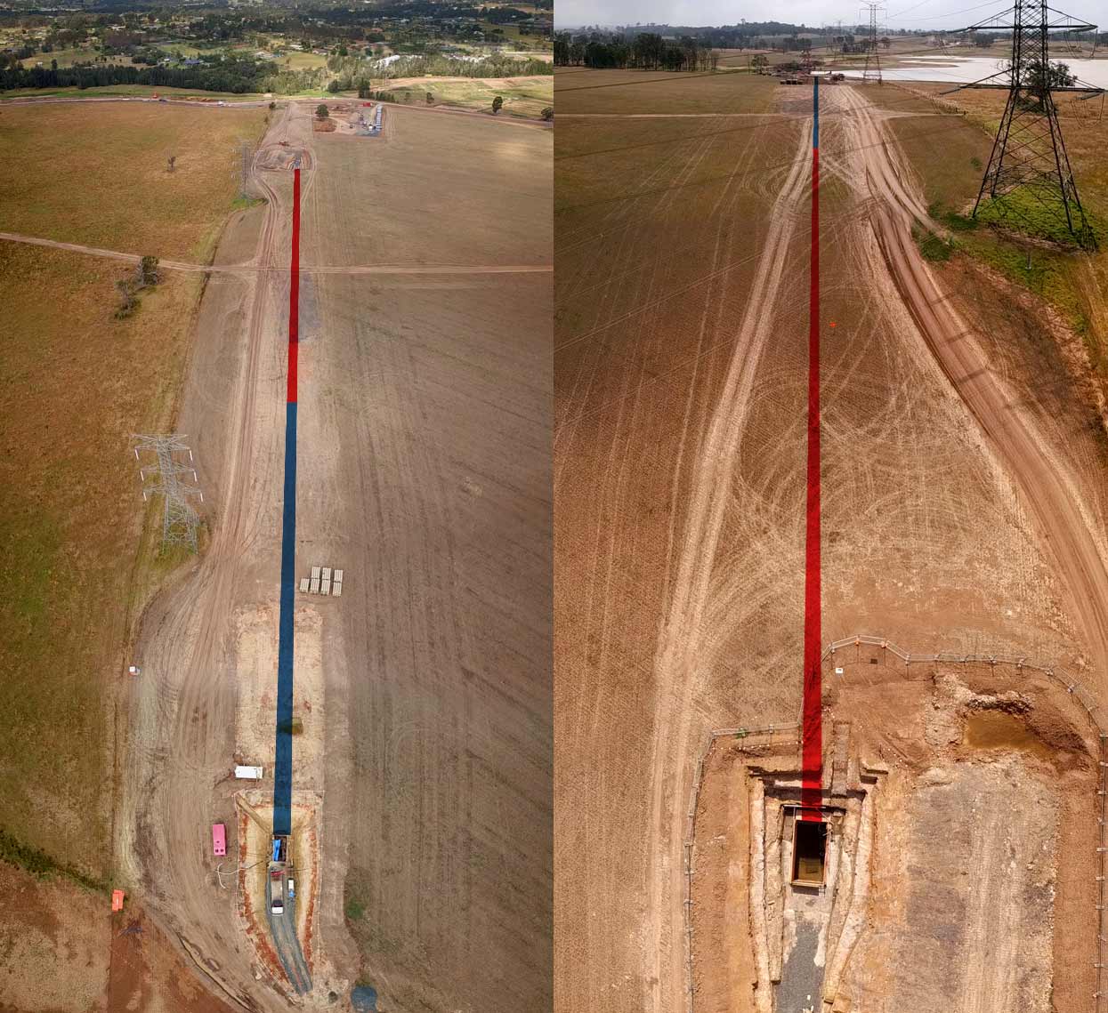
Looking down on the length of the microtunnel from shaft to shaft. (Left) Above the 120m intercept microtunnel shaft. At the top right the stockpile of GRP SN20,000 pipes which would later be sliplined into the tunnel can be seen. (Right) Above the shaft of the 197m microunnel. The proximity of the dam to the second shaft can be seen top right.
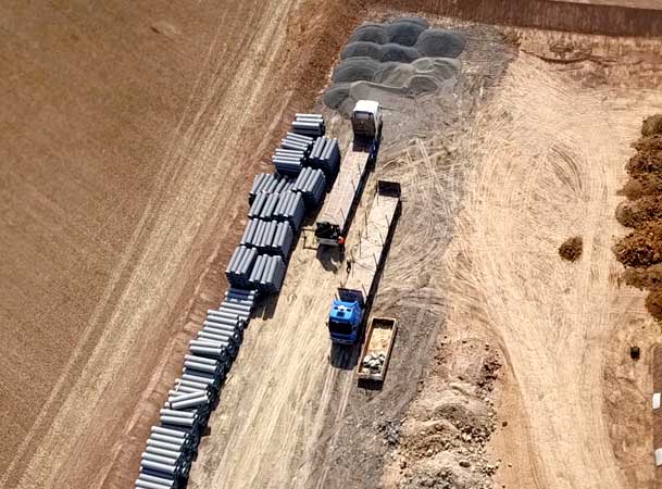
The GRP SN20,000 carrier pipes stockpile
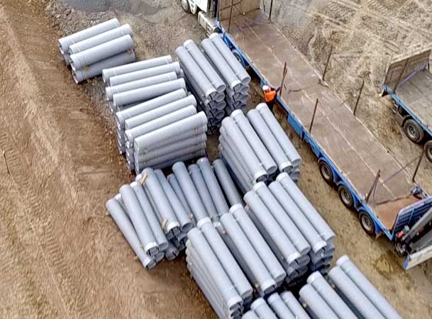
Unloading the GRP SN20,000 Carrier Pipes
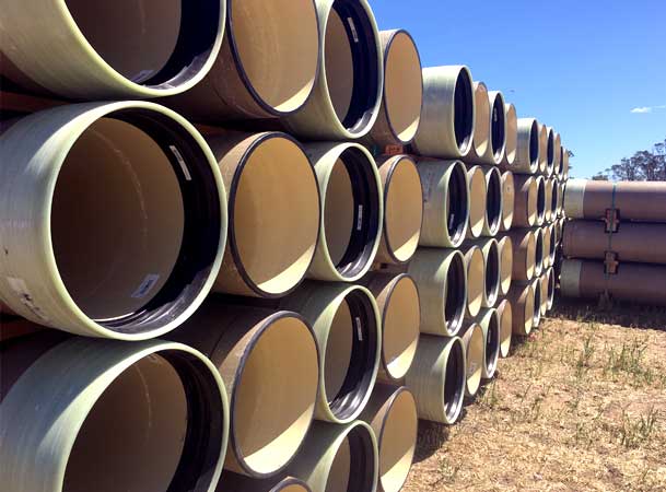
The Carrier pipes were sliplined into the 317m microtunnel.
MICROTUNNEL 1.

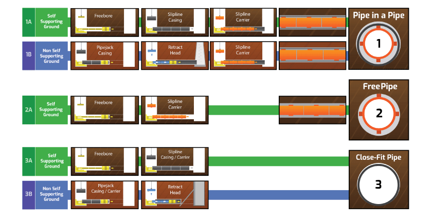
Free Pipe by Freebore Method
Length. 197m
Diameter. 560
Ground. Shale
Casing Pipe. None
Carrier Pipe. 300GRP SN20,000
MICROTUNNEL 2.

Free Pipe by Freebore Method
Length. 120m
Diameter. 560
Ground. Shale
Casing Pipe. None
Carrier Pipe. 300GRP SN20,000

