PROJECT OVERVIEW.


Tunnelling beneath Sydney Uni Oval 1
Early in the concept phase, Warren Smith and Partners approached Pezzimenti to look at the possibility of boring below the Sydney Uni Oval # 1 which is used as their Cricket and AFL oval. Under no circumstances could this oval be dug up with games being played every weekend. A geotech investigation was undertaken to determine the likely ground the bore would pass through – this is critical in determining firstly possibility and then methodology.
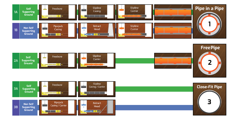
The study showed shale throughout most of the bore becoming clay and then the possibility of some fill toward the end. Given the ground conditions, it was decided to free bore (no sleeve) from the shale end to a point whereby the bore would no longer stand up in the clay.
Site Setup over a deep shaft
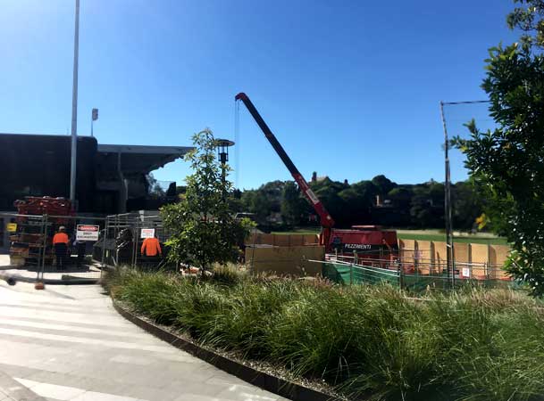
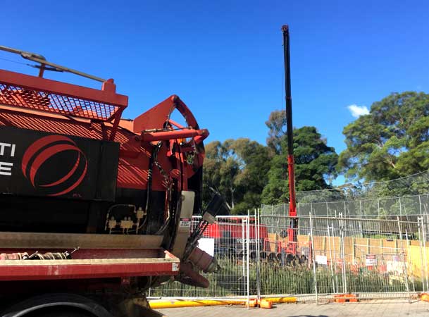
The shaft was 8m deep and had to be expanded to fit a scaffold access and a sideline drop junction – so essentially it was about twice as big as a normal shaft in a reasonably tight area. Both Pezzimenti’s crane truck and a large excavator were used for cranage as access to the shaft was difficult. All spoil was to be removed off site which meant Pezzimenti ran two bins to a registered tip. With space being at a premium, Pezzimenti managed to setup a power pack, crane truck, vacuum and two bins at the shaft.
The shale posed no problem in boring . The bore continued into the clay strata. As there was suspected fill at the other end, a free bore could not continue the full 200m as the fill was not self- supporting.
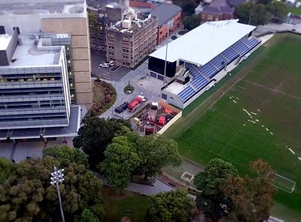
Site setup proximity with Sydney University Oval
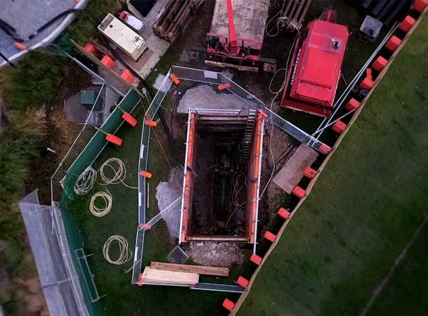
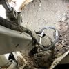
Looking down into the shaft and tight operating space
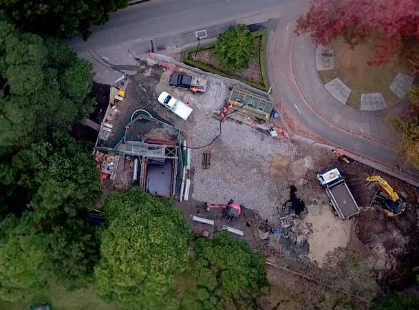
Shaft at the opposite end of tunnel
A low point in the above ground profile (3m deep) was selected to finish the first of the intercept bore – this was right at the edge of the main Oval just before the ground started to rise. The rods were retracted and steel sleeve inserted into the bore to protect it from collapse.
When the second (receive/send) shaft was dug, fill with considerable voids within was found. Therefore, pipejacking was required to meet the intercept. That being the case, an intermediate shaft where the two bores met was required so that the drilling head could be removed at that point. This was only able to be opened early in the week so that it may be backfilled and turfed come game day by the weekend.
The bore progressed through fill with all sorts of building rubbish including tin, bolts, nuts and even a horseshoe found blocking the vacuum at the shaft. The main risk here is hard material amongst soft material not breaking up and either blocking the vacuum or making a large disturbance at the face causing overcut. Without any issues, the second bore was successful and met up with the original. The head was removed and the sleeve pushed through to meet the original sleeve. The carrier main was inserted and the bore successfully grouted.
The carrier main was then installed and grouted up for a successful connection.
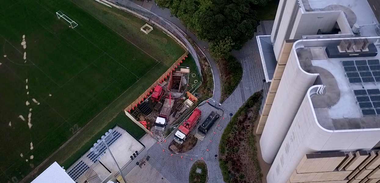
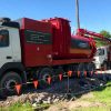
Site setup with Pezzimenti Tunnelbore equipment – Trailer Mounted Power Pack, Crane Truck, Vacuum Truck and Water Bin.
The connection to the oviform was designed to bore straight into an existing 100 year old manhole – 10m below the ground. The designer investigated the existing structure and had the design coming in above the normal flow point in the channel – as flow could not be stopped for an extended period.
The same shaft as the original bore was used (as this is the location of the connecting manhole). After going through a few possibilities with the designer and client (Diona), it was decided to bore directly into this manhole. However, it was unknown whether reo was in the structure – if so then special cutters would be required.
The carrier main was a 450GRP pipe so a connection of at least 600mm was required. Pezzimenti was prepared with steel sleeve and a special set of cutters in case the manhole contained reo.
Boring progressed up to the manhole with a 630mm head and touched the concrete. As there was no fretting in the shale, Pezzimenti were able to progress without sleeve. As there was no steel reo, the cutters made it through the manhole for the connection.
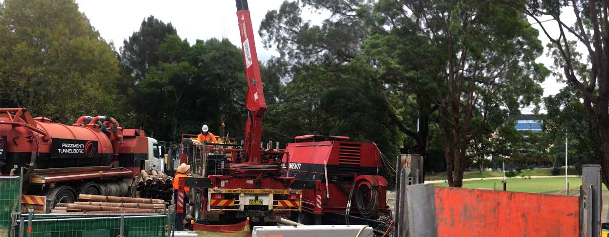
Site Setup at the second Shaft. Top men crane drill rods using the Crane Truck to the shaft, withthe vacuum truck (left) and trailer mounted hydraulic Power Pack (right)
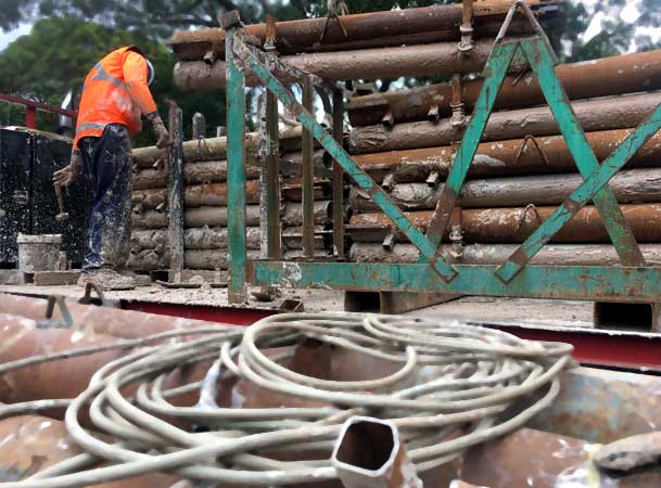
Drill Rods on the rack
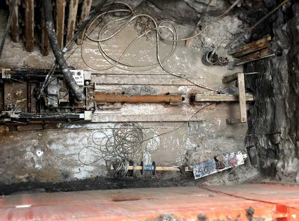
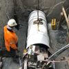
Down deep shaft with Drill rod mounted on jacking frame for free boring
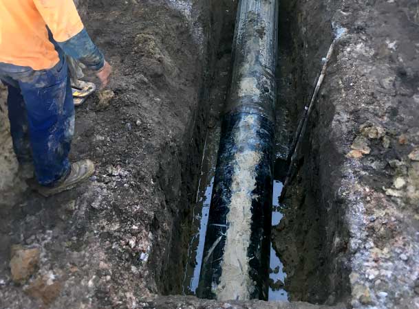
Connecting the new pipes to the old
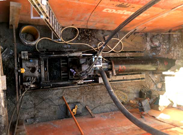
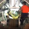
Down into deep shaft while pipjacking
MICROTUNNEL 1.

Pipe is a pipe by Freebore and Pipejack Method
Length. 201m
Diameter. 530
Ground. Shale
Casing Pipe. 508 Steel
Carrier Pipe. 300 GRP JP
MICROTUNNEL 2.

Free Pipe by Freebore Method
Length. 20m
Diameter. 630
Ground. Shale
Casing Pipe. None
Carrier Pipe. 450 GRP

